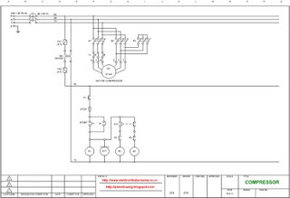
Wiring diagram compressor, star-triangle (star-delta) switching system
In most cases compressor driven by the large power motor, above 10 KW. That used to generate the huge air pressure anyway.
Example of compressor with power 30 KW (40 HP) as shown in the picture below.

To reduce inrush current (electric current of early motion) that can reach 200% to 300% of normal current when the motor will rotate, the system needs to be made such a wiring diagram star-triangle (star-delta) switching, as shown by the picture below.
 Click to enlarge
Electric parts needed for the wiring above:
1. Breaker 100 A 1 pc
2. Transformer step down 380 V / 220 V 3 A 1 pc
3. Magnetic contactor 3P 55 KW coil 220 V 3 pcs
4. Power on delay (Timer) 220 V 1 pc
5. Thermal over load relay 65 A 1 pc
6. Fuse glass 2 A dan 3 A @ 1 pc
7. Start button 1 pc
8. Stop button 1 pc
9. Motor 37 KW 380 V 3 φ 1 unit

To reduce inrush current (electric current of early motion) that can reach 200% to 300% of normal current when the motor will rotate, the system needs to be made such a wiring diagram star-triangle (star-delta) switching, as shown by the picture below.
 Click to enlarge
Electric parts needed for the wiring above:
1. Breaker 100 A 1 pc
2. Transformer step down 380 V / 220 V 3 A 1 pc
3. Magnetic contactor 3P 55 KW coil 220 V 3 pcs
4. Power on delay (Timer) 220 V 1 pc
5. Thermal over load relay 65 A 1 pc
6. Fuse glass 2 A dan 3 A @ 1 pc
7. Start button 1 pc
8. Stop button 1 pc
9. Motor 37 KW 380 V 3 φ 1 unit


Thanks gan, for information
ReplyDelete