Produce a pure wave DC from rectifier circuit
DC output generated by a rectifier circuit, not a wave of pure DC, but the waveform up and down or pulsing. These waves can not be used to distribute electronic circuits.
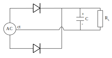
Process of flattening the pulsing waves of rectifier circuit, it can be done by connecting in parallel a large value of filter capacitor to output DC, as in the circuit below

The capacitor used is usually electrolytic capacitors (elco) and has a capacitance value of 1000 μF or more. DC pulses from rectifier circuit are generated continuously and will fill capacitor immediately, until the voltage reaches maximum value.
When the load draw current of the circuit, the voltage on capacitor bit by bit away from maximum value, but the voltage will be immediately returned to maximum value by the next pulse. The result is a DC waveform with a little wave ripple.

DC waveform with a little wave ripple like picture above, can use to supply or distribute electronic circuit. It's almost a wave of pure DC.
Process of flattening the pulsing waves of rectifier circuit, it can be done by connecting in parallel a large value of filter capacitor to output DC, as in the circuit below

The capacitor used is usually electrolytic capacitors (elco) and has a capacitance value of 1000 μF or more. DC pulses from rectifier circuit are generated continuously and will fill capacitor immediately, until the voltage reaches maximum value.
When the load draw current of the circuit, the voltage on capacitor bit by bit away from maximum value, but the voltage will be immediately returned to maximum value by the next pulse. The result is a DC waveform with a little wave ripple.

DC waveform with a little wave ripple like picture above, can use to supply or distribute electronic circuit. It's almost a wave of pure DC.


